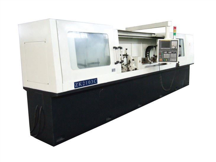
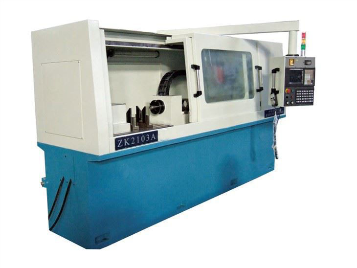
What Is The Basic Structure Of Gundrill Machine?
Apr 01, 2022
Basic Structure Of Gundrill Machine
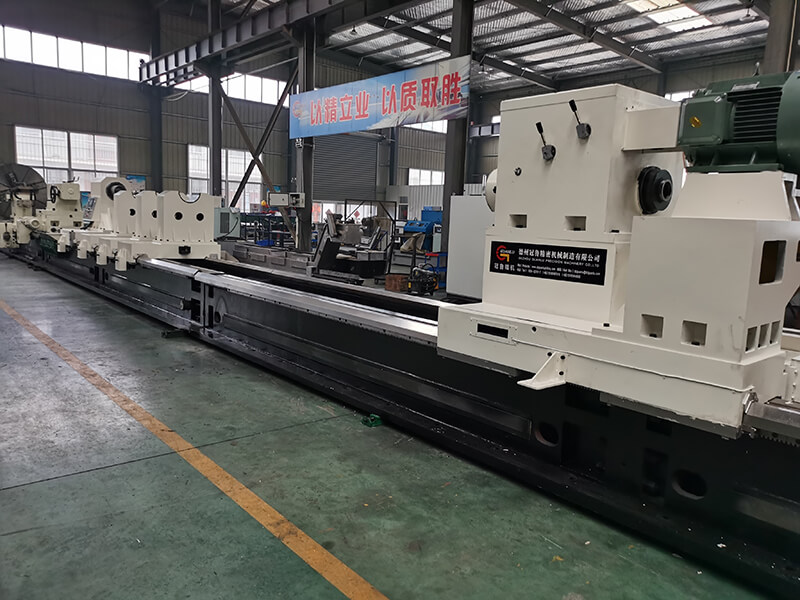
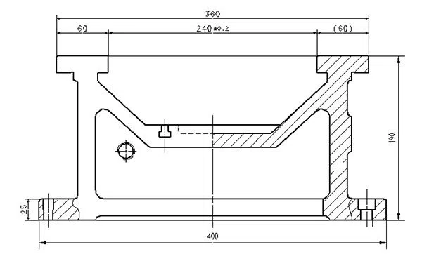
1. BED: the structure of the bed adopt three sides closed and a reasonable layout reinforcement rib, so it has the good rigidity, the headstock or hydraulic tailstock or special fixture is installed in T slot worktable and drill pipe box carriage feed on sliding table. It also has a wide and deep back oil groove around the bed, ensure the coolant liquid flow smoothly back to oil tank.
2. Headstock: there is a fixed speed. Headstock can move along axial movement according to the length of the workpiece, the rotary workpiece requires less than or equal to 100 mm in diameter. (optional part).
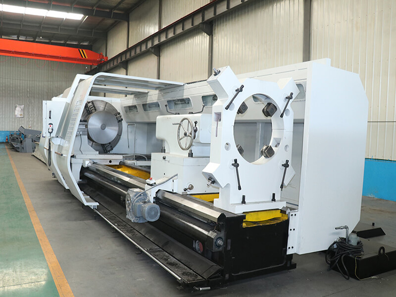
3.Drill pipe box: it adopts frequency conversion motor or spindle motor drive drill pipe rotation with stepless speed; Spindle bearings uses high precision angular contact ball bearings. Special mechanical seal device provide stable pressure and flow of cooling fluid for deep hole processing, so as to ensure the normal cutting; The drill pipe box feed carriage paste ptfe guide soft belt,which ensure the machine tool has a longer service life.
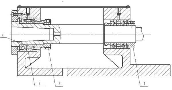
Drill pipe box spindle:
It adopts CNC system and Ac servo motor, ball screw, stepless speed. Feed speed range is 5-500mm/min. rectangular guide way of feed sliding table is treated by high frequency quenching and precision grinding, sliding table structure is three sides enclosed and a triangular stiffener rib form, ptfe guide soft belt is pasted on the surface of the slide guide rail so as to ensure the small friction coefficient and long service life, the feed system has high precision, good rigidity, smooth movement, accuracy and better stability.
Guide way of machine tool:
- The cooling system:
There are frequency conversion motor for high pressure oil pump and gear pump and other hydraulic components on the oil tank, and the machine adopts non-woven paper filter, magnet, multistage net type filtering, and forced cooling device, at the same time ,with automatic chip removal machine.
- Centralized lubrication system:
Front and back bearing of headstock and drill pipe box and slide guide rail uses automatic timing quantitative lubrication, if oil level is lower than standard value, it will have automatic alarm function.
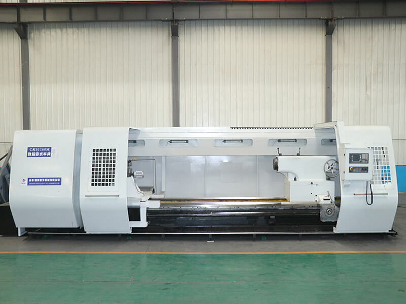
- Electrical system:
It adopt numerical control system, which can set up automatic programming processing cycle, and also can be manual, inching, opening and closing adjustment, etc. Machine tool operation button stand adopts hanging type, it makes the operator observe and operate easily and directly.
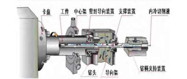
- Guide frame, according to user workpiece optional structure.
Guide frame is used for drill head orientation and drill pipe support. In the process of drilling, cutting fluid by the oil pump through drill pipe inner hole to the cutting zone, then it flow to v groove of drill pipe and cavity of the guide frame and bed body, and flow into the automatic chip removal machine, in final, it will be sent to the storage crumbs.
- Guide frame front end structure is divided into four kinds, corresponding to different usage.
A. guide sleeve rotating but don't axial movement.
B. guide sleeve not rotating but axial movement.
C. guide sleeve not rotating and axial movement.
D. guide sleeve rotation and axial movement.
- Drill pipe bracket:
It is used for the drill pipe support and reduction of vibration, it can equip with electric moving.
- Hydraulic system:
Hydraulic system is to provide pressure oil to the moving oil cylinder. It is used for against, loose or work inlet oil sealing role with electric control system.
- Workpiece support bracket: (optional part)
It is used for support to the workpiece. The workpiece bracket place support range is φ 8 - φ 50 mm or φ 50 - φ100 mm.
- Steady rest: (optional part)
It is used for place workpiece and have fixed function. The workpiece bracket place workpiece range is φ 8 - φ 50 mm or φ 50 - φ100 mm.
Max workpiece diameter clamping range of double axis and four axis is Φ 85 mm
- Hydraulic tailstock: (optional part)
It is installed in T slot workbench, it can be adjusted and fixed according to the size of the workpiece length. Against and loosen the workpiece through the oil cylinder control plunger so that it can make axial movement.
- Special fixture: (optional part)
We design it according to customer's drawings in order to satisfy the requirement of workpiece machining.
- Protective cover:
The machine adopts fully enclosed protection, which have enough operation space and wide field vision.
Previous: No Information